The project is part of an experimentation I did in Creation & Computation class at OCADU, in fall 2025. As I was making this as a first project in OCAD, without any clear idea for my thesis, it reminded me of how much “digital craft” might be an important thread to follow along in my future exploration.
Haptic Kumihimo: Measuring Force in Braiding
Concept
When I knit or braid, keeping a consistent texture means constantly judging whether the string is too tight or too loose. With Kumihimo Japanese braiding craft known for its intricate pattern, this consistency requires skill and experience. I was especially struck by a Kumihimo artist who said the braid reflects the maker’s inner state. It made me wonder: what if the tension on each string could be sensed and expressed back to the maker in real time?
When I finally created a simple, intuitive feedback system, I was surprised by how natural and useful it felt. In the video, for example, when a white light signaled that the string was too tight, I immediately adjusted the tension before moving on to the next cycle.
Iteration
Capturing tension in a thin thread required multiple iterations.
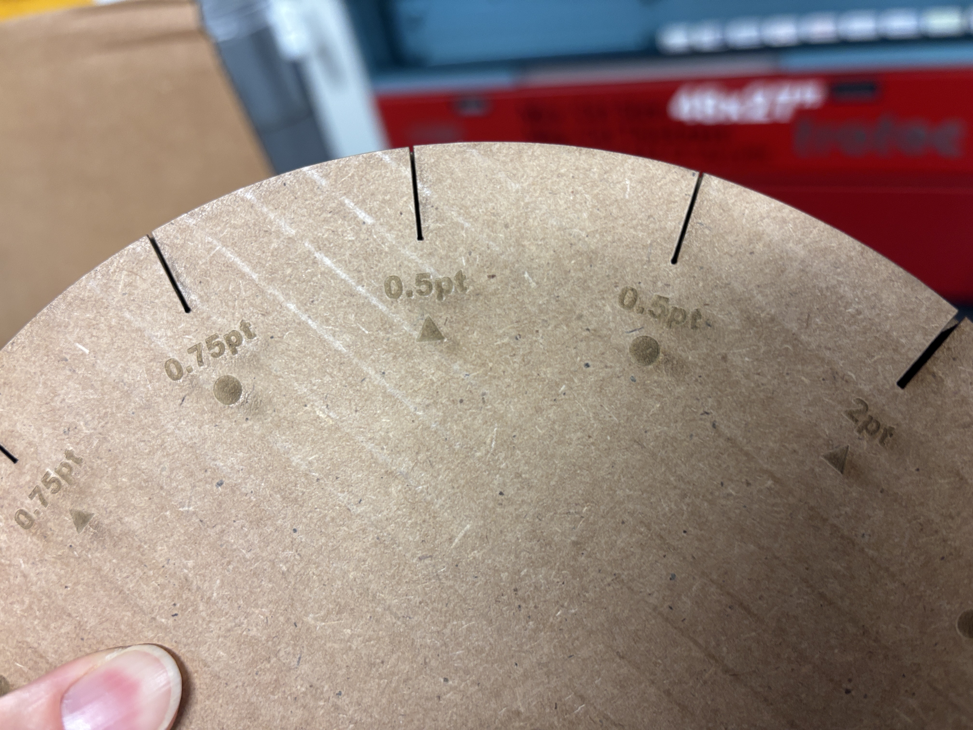
- Slit design: A 0.5 pt slit with a straight-bottom triangle cut best held the string without slipping, nor too tight.
- Pressure sensing: Detecting tension directly at the slit edge was unreliable because the contact area was too small. Adding a small bump so the string could press more firmly onto the surface made the DIY FSR respond consistently. A quick prototype with a felt ball confirmed the idea worked.
Attention to detail
Because the concept depends on subtle feedback, the final design focused on detail.
- Lighting feedback: I replaced abrupt blinking with a smooth fade-in/fade-out cycle. This reduced distraction and gave the tool a calming, breathing feel.
- Tactile quality: Traditional Kumihimo uses wooden bobbins that create a rhythmic sound. I recreated this effect by crafting simple wooden bobbins from sticks at the wood shop.
Material behavior
The biggest challenge came before the exhibition. I treated the piece as a static design and didn’t anticipate how much stitching and assembly would affect the sensing capacity of the DIY FSR. Although I tested it during the build, I only noticed the growing noise and random lighting once everything was fully enclosed and difficult to adjust.
After the exhibition, I disassembled the piece and monitored the data in real time while reassembling it. I found that even small changes, such as taping over copper and velostat layers or adding felt balls, dramatically reduced resistance, even before stitching.
![[serial monitor.jpg]] Continuous testing revealed how quickly the material responded to every modification. As a result, I:
- Stopped using tape and used thin paper to sandwich the DIY FSR to stay in place instead.
Before:
 After:
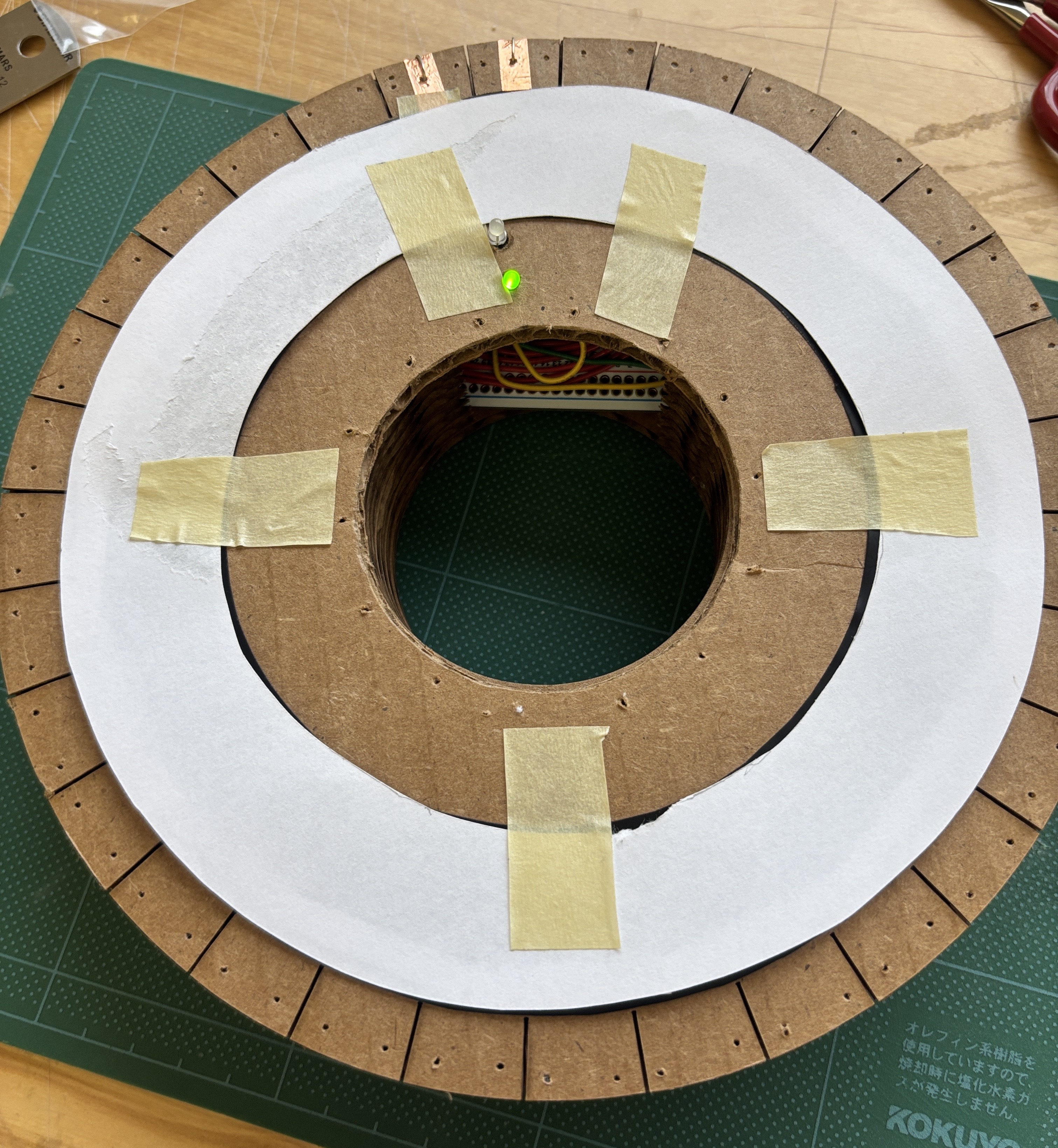
- Replaced bulky felt balls with light cotton string to apply pressure, it turned out to be enough to function as a bump.
Before:
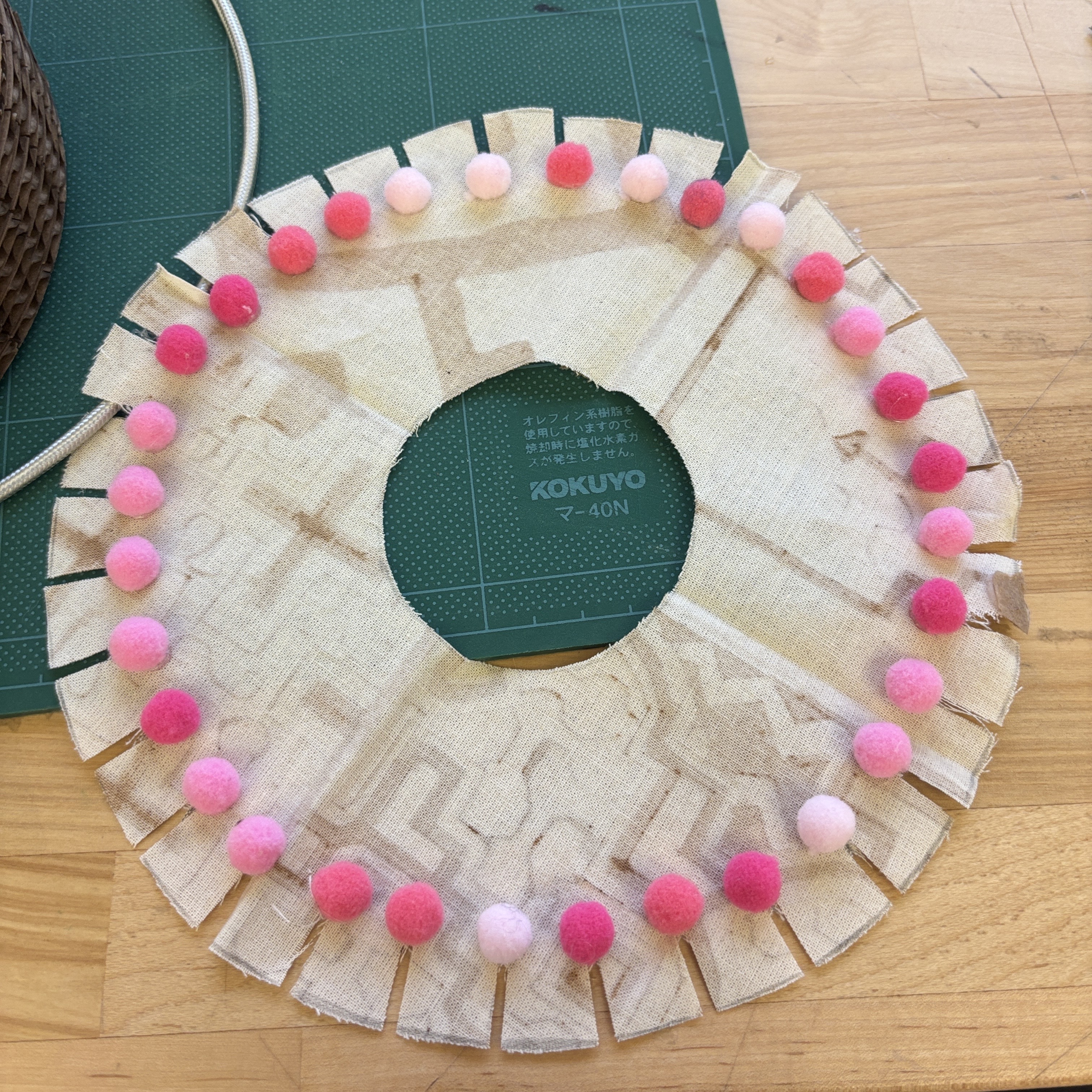 After:
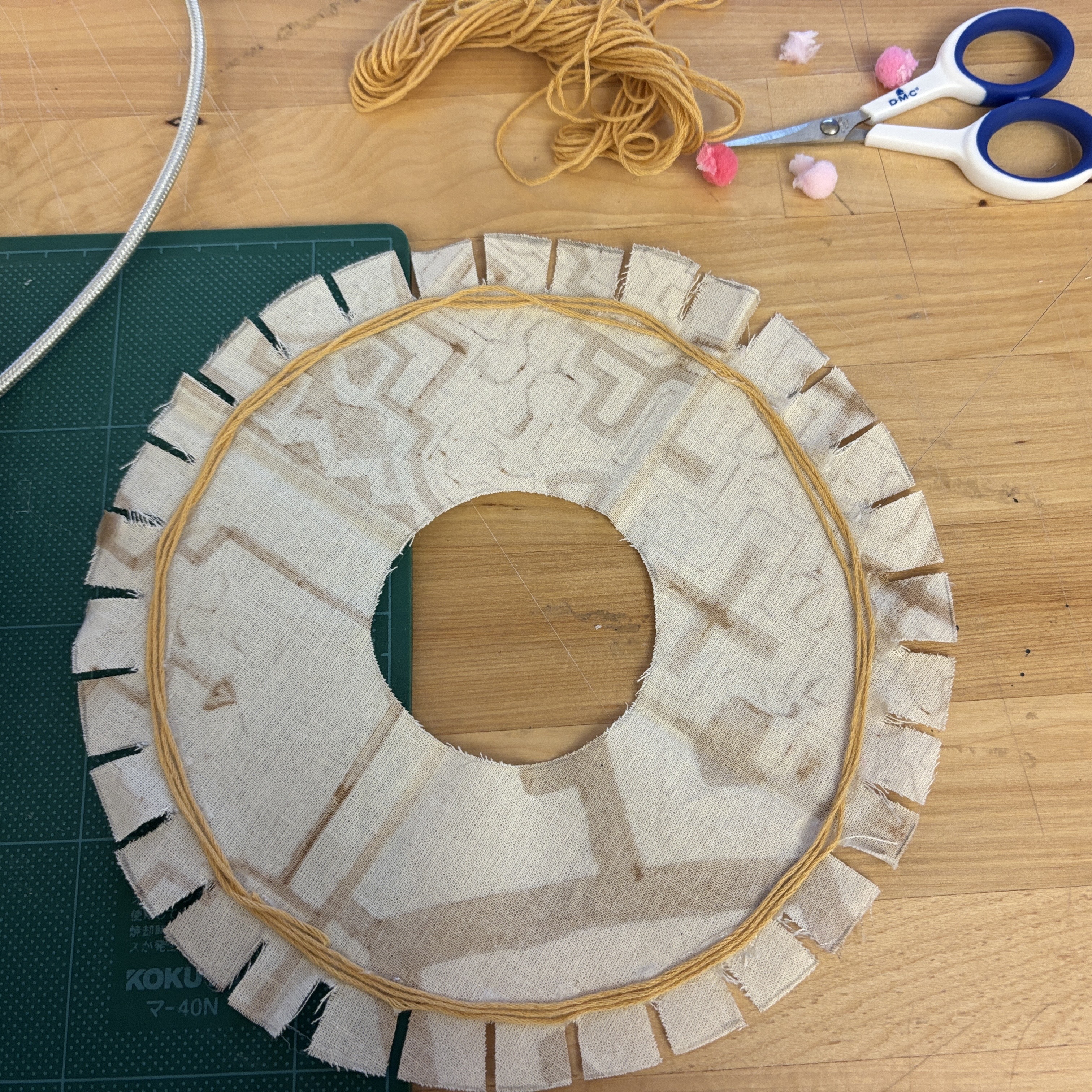
- Switched from 1/16” styrene to light fabric, attaching it without tension to preserve the sensor’s sensitivity.
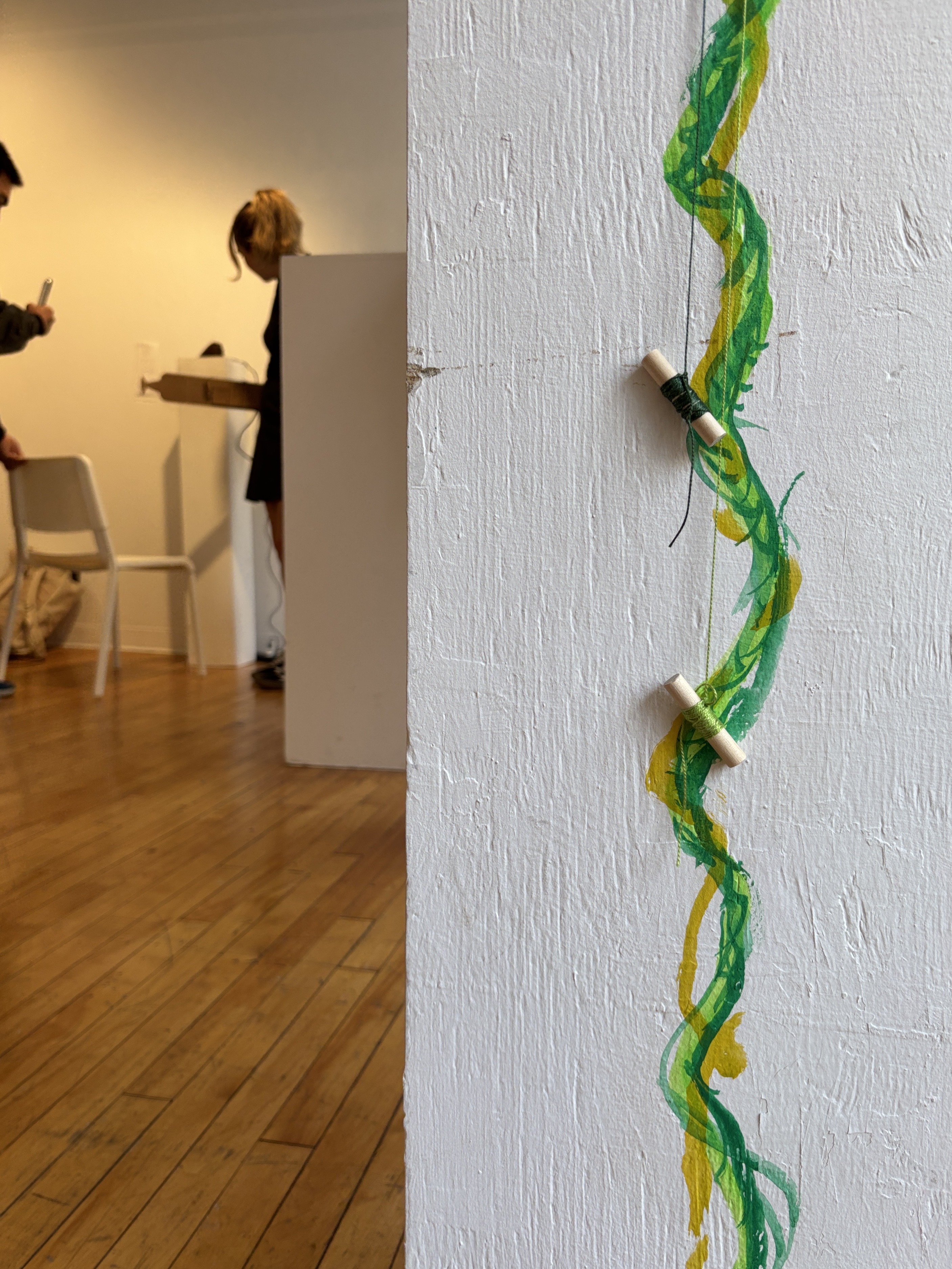
Before: ![[at exhibition.jpg]]
After:
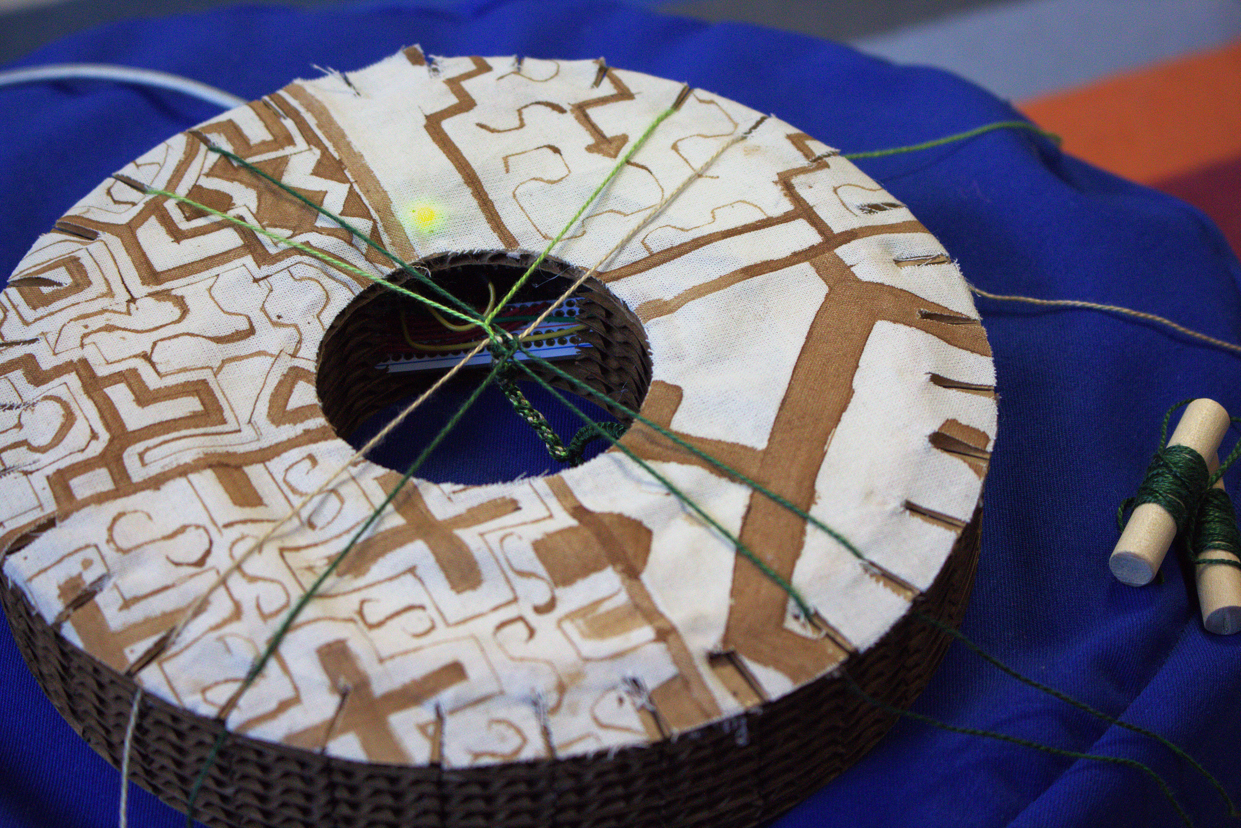 These adjustments kept the sensing consistent and responsive in the final build, as shown in the previous videos.
Circuit
The circuit connects an Arduino Nano to the FSR with a simple voltage divider circuit using resistors, reads analog values from the FSR (A6), and switches the LEDs accordingly based on the measured force for real-time visual feedback (~11, ~12):
- Low pressure lights up green LED (~11) that signals “Good, carry on”,
- High pressure lights up the white LED (~12) to demand attention and “Be gentle”.

Code Narrative
Find the entire code here: a1_kumihimo_pressure_sensing.ino
How it works:
- Reads analog values from
A6. Values are scaled to 0~100 and compared to athreshold. - Uses decision logic to decide which LED is active:
- Above threshold ( 70 on the 0~100 scale) -> White LED fades in
- Below threshold -> Green LED fades in
- Brightness increases or decreases between 0~255 using
analogWrite(). Direction flips at each limit for a smooth pulse. millis()timer updates brightness every 10 ms (fadeInterval).- Prints raw and mapped sensor values for debugging purposes.
Continued
Later, after a few months, I made this prototype again hoping to achieve a final phases of prototype that’s ready for the end of the year Digital Futures Open Show. It didn’t go as planned.
I was surprised to re-learn, that even though I thought I knew everything by then, I still stumbled, even if the process was updated, caution points were forgotten, and replacing the materials (and tools) added new considerations,
Next actions
Some key points that I need to work on:
How to keep the tension sensing capacity of the velostat? Every time I struggled to keep the pressure sensing range of the velostat when I started to stitch/glue things together. Below are some of the measurements I’m looking to experiment:
- Replace voltage-divided circuit’s resistor with a potentiometer that can shift the resist to leave more room for calibration
- Update the Arduino code to add in a calibration sequence. So that initially, the lowest and highest value should be monitored and saved, then within that range, change in pressure should be measured
Don’t do things that’ll add pressure onto the velostat. The fabric layer with some fillings to make a bump worked well in the second prototype when there was no tension on the fabric when it was adhered to the disc. However, in the latest prototype, as I look to “refine the look”, which usually meant smoothing out the crease with fixing, it added too much stress to the velostat underneath.
- As I learnt to use felt, which I used to just use it as a filling, I can directly make a piece of formed cover for my disc. I won’t use glue, since it messed with the surface (which prompted me to paint over and it was a disaster), I want to drill some tiny holes on both outer and inner rims to thread the felted piece with the disc.
- Smooth out the edge of the disc, taper it using rotating bits
- Use a sew to clean out the thread holder
For both thread holder and threading holes, it seems to be best done after the whole piece is assembled and glued together, since they are too small to be aligned properly. It requires hand, as it’s too thick for laser cut, and there would be a arduino living inside.
